
 HOTLINE:+8613974960765 +8618507312158 HOTLINE:+8613974960765 +8618507312158


— Knowledge —
— PRODUCTS —
 Service Hotline +8613974960765
Email:susie@hnljpump.com
Mobile:+8618507312158
TEL:+8613974960765
vertical turbine pump
Publication date:2025/10/29 23:32:24 popularity: [content:visits]
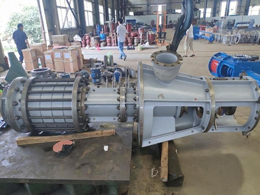
This selection guide for vertical Multi-stage barrel-type condensate Turbine Pumps covers the entire process from core parameter verification, scene adaptation, to key points to avoid pitfalls. It allows for direct comparison and selection, avoiding system failures caused by parameter mismatch.
This is the core foundation for the selection of vertical barrel-type vertical condensate pumps (condensate pumps), which directly determines whether the Condensate Turbine Pumps unit can adapt to the system operating conditions:
Flow: Selected based on 110%-120% of the system's maximum condensate flow, ensuring sufficient delivery margin under full load and transient operating conditions of the unit, to avoid thermal cycle imbalance caused by insufficient flow.
· Head: It is necessary to fully cover the three core components: negative pressure resistance of the condenser, frictional loss along the pipeline, and high-level difference of the deaerator. A margin of about 10% should be reserved to avoid serious failures such as vacuum system collapse caused by selecting a lower head of 0.3 MPa.
Net Positive Suction Head (NPSHr): The required NPSHr of the pump must be less than the NPSH of the system device. The actual NPSH calculation formula is: (atmospheric pressure - condenser vacuum) - suction height - pipeline loss, to completely eliminate cavitation damage under high negative pressure conditions.
Temperature compensation: For every 10°C increase in medium temperature, the head will decrease by approximately 1%. For condensate water at temperatures above 80°C, additional correction of the head parameters is required to avoid insufficient head during actual operation.
Efficient Zone Matching: Verify the flow-head curve provided by the manufacturer to ensure that the daily operating point falls within the efficient range of 70%-120% of the pump's rated flow, avoiding long-term operation outside the efficient zone that could lead to a surge in energy consumption.
Select the corresponding configuration based on the characteristics of the working conditions to significantly extend the lifespan of the equipment:
Basic Material: For conventional clear water condensate scenarios, the pump casing is made of ductile iron, while the impeller is constructed from 304 stainless steel, balancing strength and corrosion resistance while minimizing hydraulic losses.
· Severe condition upgrade: For petrochemical and overseas power projects, models that comply with the international standard API610 (11th edition) are preferred. They have an average trouble-free operation time 40% higher than ordinary products and are suitable for scenarios with high corrosion and high continuous operation requirements.
· Shaft seal configuration: Single-end mechanical seals are selected, with the sealing water pressure required to be 0.1-0.2 MPa higher than the pump chamber pressure. The condensate water delivered by itself is used as the sealing water source throughout the process to avoid polluting the boiler feedwater quality.
· Anti-cavitation structure: For high negative pressure conditions, the preferred choice is the first-stage double-suction impeller structure with an inducer. This design approach reduces the risk of cavitation from the outset, preventing honeycomb-like erosion pits on the impeller.
For the differentiated needs of different industries, we precisely match the optimal solution:
Large thermal/nuclear power plants: Priority should be given to models with core-pulling maintenance structures, which allow the rotor to be extracted for maintenance without dismantling the pump body. These models are suitable for the long-term continuous operation of multi-million-kilowatt units, reducing operation and maintenance downtime.
· Small and medium-sized thermal power plants/captive power stations: Focus on the optimized energy-saving hydraulic model, which can reduce energy consumption by 7%-12% compared to older equipment, significantly reducing the long-term operating costs of heating in industrial parks and captive power stations for industrial and mining enterprises.
· Renovation of old units: Prioritize manufacturers with full-chain manufacturing capabilities, support the replication of complete sets of accessories such as old pump rotors, impellers, and balance discs without requiring drawings, and directly replace old pumps without modifying existing pump room pipelines, significantly reducing the cost of renovation and adaptation.
· Special chemical conditions: When the medium exhibits mild corrosivity, the flow-through components are upgraded to 316 stainless steel; in high-corrosion scenarios, duplex steel is selected to prevent component failure due to medium corrosion.
⚠️ Post-model selection, avoid pitfalls with complementary configurations
90% of users tend to overlook these details, which directly affects the service life of the pump unit:
A minimum flow bypass valve with a capacity of 30% of the rated flow must be equipped to prevent the medium inside the pump from overheating and vaporizing during low-load operation of the unit, which could lead to the pump unit failing to pump water due to air binding.
Ensure that the inlet and outlet pipe diameters of the pump assembly perfectly match the on-site piping. Preferably choose a structure where the inlet and outlet can be rotated by integer multiples of 15°, allowing for a 180° rotation, to fit the compact layout of the pump room without requiring additional piping modifications.
Confirm that the energy efficiency rating of the supporting motor is not lower than IE3, and it is compatible with 380V/10kV on-site power supply conditions to avoid overload tripping caused by power mismatch.
Related Recommendations

Service hotline
screenshots ,WeChat Scan the Qr Code
WeChat:ljpump6666